


What belongs in a Slant Bed CNC Lathe supplier acceptance test?
What Belongs in a Slant Bed CNC Lathe Supplier Acceptance Test?
A slant bed CNC lathe may appear ready for shipment when the control powers up, the turret indexes, and a sample part looks acceptable. That is not enough for a meaningful supplier acceptance test. For quality control and safety managers, the real question is whether the machine can repeatedly produce the required work under realistic conditions while protecting operators, supporting maintenance, and meeting the agreed technical specification.
A thorough acceptance test should be agreed before the machine is built, not improvised during final inspection. The purchase specification, approved layout, sample-part drawing, control configuration, tooling package, and applicable local safety requirements should all be reflected in the test protocol. A capable Slant Bed CNC Lathe supplier should be prepared to demonstrate more than basic axis movement. The supplier should provide measurable evidence of machine accuracy, functional reliability, safety performance, and delivery completeness.
Start with the Acceptance Plan, Not the Machine Demo
Factory acceptance testing is most effective when it has clear pass/fail criteria. “Machine runs normally” is too vague to resolve disputes later. The buyer should identify which characteristics matter most to the intended work: tight diameters, concentricity between operations, turning surface finish, bar work stability, heavy interrupted cuts, or unattended production. A lathe intended for short precision shafts needs a different emphasis from one intended for larger flanges or valve components.
Before testing begins, confirm the machine model, bed length, spindle motor and speed range, chuck or collet arrangement, turret station count, controller version, axis travels, coolant arrangement, chip conveyor, hydraulic unit, and electrical supply assumptions. Any approved options should appear on the inspection record. This prevents a common problem: a machine is tested in a configuration that differs from the machine eventually packed for export.
Where a formal accuracy method is required, the parties can reference the relevant machine-tool test methods or an agreed customer standard. The exact tolerances should come from the contract, machine specification, and intended process capability rather than from generic claims.
Geometric Accuracy and Axis Performance
A slant bed design supports chip evacuation and often improves operator access, but its geometry still needs close verification. Acceptance should examine leveling provisions, bed condition, linear guide installation, turret alignment, spindle centerline relationship, and tailstock alignment where a tailstock is supplied. Inspection methods may include calibrated indicators, test bars, precision levels, or laser-based measurement systems, depending on the agreed scope.
Axis positioning alone is not the whole story. Test both positioning accuracy and repeatability across meaningful portions of X- and Z-axis travel. Repeatability is especially relevant for production work because a lathe can reach a commanded point once yet drift in repeated cycles due to backlash, servo tuning, thermal effects, or mechanical friction. The test record should state measuring equipment used, environmental conditions where relevant, test locations, readings, and allowable deviation.
Turret indexing deserves separate attention. Run repeated indexing cycles through every station, then verify that the selected station locks securely and returns consistently. A turret that intermittently loses position may not show a problem during a short demonstration, but it creates a serious risk of damaged tools, scrap parts, or collisions after installation.
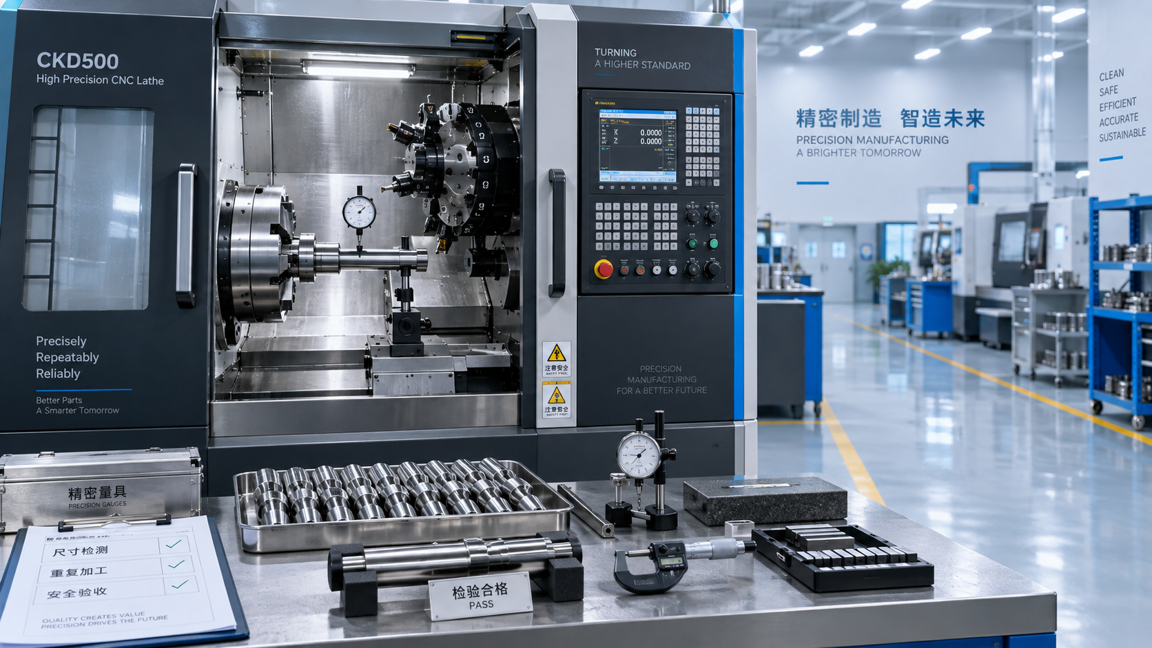
Spindle, Chucking, and Cutting Tests
The spindle test should include runout verification at the spindle nose and, where appropriate, on a suitable test bar or workholding interface. The supplier should demonstrate operation through the required speed range, including acceleration, deceleration, direction changes, and sustained running at an agreed speed. Listen for abnormal bearing noise, observe vibration, and confirm that the control displays actual spindle speed reliably.
Workholding cannot be treated as an accessory detail. Check chuck mounting, jaw condition, hydraulic clamping response, pressure indication, foot-pedal or command operation, and any interlocks intended to prevent unsafe spindle start. If the project involves bar feeding, sub-spindle transfer, tailstock support, or automatic parts collection, those functions should be exercised as an integrated sequence.
A practical cutting trial gives meaning to geometric measurements. The agreed test workpiece should reflect the planned material and process where possible. A useful sample may include facing, external turning, boring, grooving, threading, and a diameter transition requiring both X and Z movement. Evaluate dimensional results, taper, roundness where it is critical, surface appearance, burr formation, chip control, and cycle stability. One successful part is encouraging; several repeated parts provide stronger evidence that the process is stable.
Safety Must Be Tested as a System
Safety review should cover the actual delivered configuration, not only the machine brochure. Verify the enclosure, door integrity, viewing window condition, door interlock behavior, emergency-stop devices, warning labels, guarding around rotating components, and containment of coolant and chips. Opening an interlocked door during an appropriate test sequence should produce the expected machine response. Emergency stops should be checked from each installed location, followed by a controlled reset and restart procedure.
Electrical inspection should include cabinet cleanliness, wiring identification, grounding arrangements, protective devices, cable routing, ventilation, and safe access for servicing. Electrical standards and conformity requirements vary by destination market, so the required documentation and machine configuration need to be established in advance. Safety managers should also verify that hydraulic, pneumatic, coolant, and lubrication systems show no leaks under operation and that low-level or fault alarms function as specified.
Do not overlook recovery behavior. Simulate only safe, agreed fault conditions, such as a door-open signal, low lubrication alarm, or controlled interruption of a cycle. The objective is to confirm that the machine stops predictably, provides a clear alarm, and can be returned to service without bypassing protective functions.
Controls, Documentation, and the Handover Record
The CNC control should be tested from an operator’s perspective: program loading, manual jog, reference return, offset entry, tool-life functions if included, alarm history, backup procedures, and communication interfaces. Confirm the language version, electrical voltage, frequency, and controller software against the order. If the machine is supplied with automation, interface signals and safety logic should be included in the acceptance scope rather than deferred until commissioning.
A complete handover package usually includes the machine layout, foundation and installation requirements, electrical and pneumatic diagrams where applicable, lubrication information, operation manual, maintenance instructions, spare-parts list, control backup, inspection records, and packing list. Toolholders, soft jaws, manuals, keys, leveling pads, and special accessories should be physically counted before packing.
This discipline applies across a machine-tool fleet. For example, the acceptance of a Vertical Drilling Machine Z5040A would focus on different process risks, including its 40 mm maximum drilling capacity, M24 tapping capability, MT4 spindle taper, 180 mm spindle travel, feed selection, and table adjustment. The principle remains the same: confirm the quoted capability through inspection and functional testing, then document what was accepted.
A Better Basis for Supplier Evaluation
The best acceptance test is not necessarily the longest one. It is the one that addresses the failure modes most costly for the intended application: unstable dimensions, unsafe access, poor chip control, unreliable turret operation, insufficient documentation, or difficult service access. Any deviation should be written into a punch list with responsibility, correction method, and closure evidence before shipment approval.
Shandong Honcan Machinery Equipment Co., Ltd. approaches machine-tool delivery through the linked priorities of innovation, quality, and reliability. For buyers, that should translate into a transparent test process: technical requirements defined early, measurements recorded clearly, safety functions witnessed, and configuration details checked before the equipment leaves the factory. A well-run supplier acceptance test does not eliminate every commissioning task, but it gives the receiving team a far more reliable starting point for installation and production.
