


Choosing cutter diameters that match the Magnetic drill VD50 capacity
A cutter diameter should be selected against the usable working envelope of a Magnetic drill VD50, not against the largest cutter that can be physically mounted in its arbor. The practical limit is set by the combined effect of motor torque, spindle speed, magnetic holding force, cutter geometry, workpiece condition, and feed control. A diameter that appears acceptable on a specification sheet can still produce poor holes, cutter breakage, or unsafe machine movement when those conditions are unfavorable.
For technical evaluation, the safest starting point is to treat the stated maximum diameter as a boundary rather than a routine operating target. Regular production work is usually more reliable when the chosen annular cutter leaves margin for material variation, surface condition, and operator handling. The closer the job moves toward the VD50's upper diameter range, the more important it becomes to verify the full drilling setup rather than considering cutter diameter alone.
Begin with the cutter type and the real hole requirement
The first selection question is whether the hole truly requires a large annular cutter. Annular cutters remove a ring of material rather than converting the whole hole volume into chips, which makes them efficient for structural steel, fabrication, maintenance, and plate work. However, efficiency does not eliminate the mechanical demand created by a larger cutting circumference.
Diameter should be specified together with cutter depth, shank style, and tooth form. A 40 mm shallow-cut high-speed-steel annular cutter is not equivalent to a 40 mm long-series carbide-tipped cutter. The longer cutter has more engagement time, more chip evacuation demand, and greater sensitivity to feed interruption. Carbide-tipped cutters can offer an advantage in harder or abrasive materials, but they can also be less tolerant of vibration, intermittent contact, and misalignment than a well-chosen HSS cutter.
Technical evaluators should define the hole requirement in a form that exposes these differences:
- Finished hole diameter and tolerance required after drilling.
- Material grade, hardness condition, and whether the surface is coated, painted, rusty, or laminated.
- Material thickness and whether the cutter must pass through one plate or several interfaces.
- Required cutter depth, including any clearance needed below the workpiece.
- Hole position relative to edges, welds, bends, stiffeners, and existing holes.
When a hole will subsequently be reamed, tapped, or bolted through with generous clearance, the drilling diameter may be chosen differently from a hole that must function as a precise locating feature. Avoid selecting a larger cutter simply to reduce a secondary operation unless the drill and workholding can preserve the required positional accuracy.
Torque and speed determine whether the diameter is usable
As cutter diameter increases, the drill must sustain higher cutting torque. The cutter may still rotate at no load, yet stall or chatter as soon as the teeth enter the material. For a Magnetic drill VD50, this is why a maximum-diameter claim should be read with the rated power, gearbox arrangement, rated drilling speed, and recommended cutter range.
Large annular cutters generally operate at lower speeds than small cutters. If speed is too high, tooth temperature rises, edge wear accelerates, and the cutter can lose hardness or chip prematurely. If the speed is too low for the cutter and material combination, cutting can become unstable and the operator may compensate with excessive feed force. The correct operating point is a balance: enough feed to keep each tooth cutting, but not enough to overload the machine or weaken magnetic stability.
Do not use unloaded rpm as proof that a cutter diameter is suitable. Drilling performance depends on loaded speed and available torque. Evaluators should ask for the recommended speed range for the intended cutter diameter and material, then confirm whether the machine provides a suitable low-speed setting or mechanical gear range. This matters particularly on thicker mild steel, stainless steel, alloy plate, and situations where coolant access is restricted.
A practical assessment can divide planned diameters into three groups: routine sizes, occasional upper-range sizes, and sizes outside the intended machine envelope. Routine sizes should cover the bulk of the work with predictable cutter life. Upper-range sizes may be acceptable for controlled jobs with clean material, sound holding conditions, and appropriate cutters. If the required diameter sits at the upper boundary on most jobs, the more appropriate decision may be a larger-capacity magnetic drill rather than repeatedly operating the VD50 at its limit.
Magnetic holding force is part of diameter selection
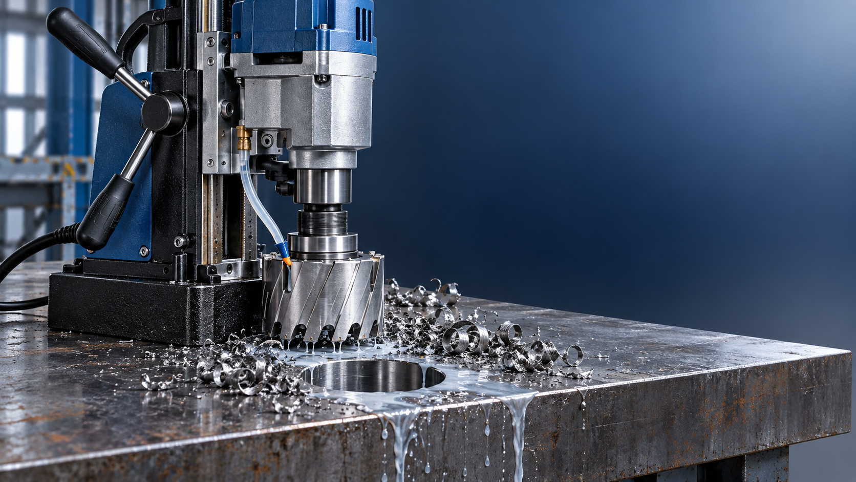
The magnet does not merely prevent the drill from falling. It resists the rotational reaction generated during cutting and helps maintain the cutter axis relative to the hole. Larger diameters raise this demand, especially when the cutter first contacts the workpiece, breaks through at the underside, or encounters a hard spot.
Published magnetic holding force is normally associated with favorable steel contact conditions. Real workpieces can be less forgiving. Thin plate may flex. Scale, paint, rust, weld spatter, and uneven surfaces reduce effective contact. Curved stock and narrow flange work can leave insufficient area beneath the magnetic base. Material with lower magnetic permeability may also be unsuitable for a conventional magnetic drill regardless of nominal cutter diameter.
Before approving a large cutter, verify the drill's support condition at the actual drilling location. The base should sit fully on a clean, flat ferromagnetic surface with adequate thickness and area. The machine should be secured with the appropriate safety restraint even when magnetic adhesion appears strong. Do not regard a strong magnet rating as permission to drill near an edge, across a lap joint, or on distorted plate without additional assessment.
Hole location often changes the answer. A 50 mm cutter may be manageable at the center of a stable steel plate but inappropriate near a free edge or beside a weld seam. The same applies to overhead and vertical drilling, where operator control, chip management, and safety restraints deserve more conservative limits.
Material thickness changes the load more than many buyers expect
Diameter is visible, but cutting depth is frequently the factor that turns a feasible hole into a poor process. A cutter drilling through 10 mm plate has a short engagement period. Through 50 mm material, it must maintain alignment, lubrication, chip clearing, and tooth integrity over a much longer path. Larger diameter combined with maximum cutting depth is the most demanding case and should not be assumed from a single maximum-diameter figure.
For thick material, match cutter depth to the job rather than choosing an excessively long cutter by default. An unnecessarily long cutter increases overhang and can reduce rigidity. It may also complicate chip evacuation. Use a cutter with sufficient depth for the material and breakthrough allowance, while preserving the shortest practical cutting assembly.
Stacked plates create another risk. The cutter can catch at the interface between layers, and chips may pack between surfaces. Where drilling through assembled sections cannot be avoided, the process should be evaluated as an interrupted or variable-load operation. It may require a reduced feed, more frequent cleaning, and a more conservative diameter choice.
Check the interface, stroke, and surrounding clearance
A cutter can fall within a drill's nominal capacity and still be incompatible with the actual setup. Confirm that the cutter shank matches the arbor and that the pilot pin, coolant delivery arrangement, and ejector mechanism are correct for the cutter depth. An improvised adapter may introduce runout or reduce rigidity, which becomes increasingly harmful as diameter rises.
Feed stroke also deserves attention. The drill must have enough travel to bring the cutter through the full material thickness while allowing the cutter to start, penetrate, and clear the slug. Nearby structural members can obstruct the motor housing or feed handles before the hole is complete. These issues are common in shipbuilding, structural fabrication, and maintenance work, where access may be tighter than the drawing suggests.
Where hole sizes are consistently modest, a smaller machine can offer better handling and faster setup. For example, the Magnetic drill VD16E is positioned for drilling up to 16 mm, making it more relevant for light-duty hole work than a larger-capacity unit intended to cover a broader annular-cutter range. Matching machine size to the dominant hole population can improve portability without forcing a high-capacity drill into unsuitable access conditions.
A defensible selection approach
Approve cutter diameters for a Magnetic drill VD50 by building a simple job matrix rather than choosing from a single maximum value. List the intended diameters, cutter depths, materials, orientations, and hole locations. Identify which combinations are routine and which require controlled conditions. The result should show where the VD50 has comfortable operating margin and where a larger drill, different cutter technology, supplementary fixturing, or a different drilling method is justified.
The most reliable cutter choice is usually the smallest diameter that satisfies the drawing and assembly requirement, paired with a cutter depth appropriate to the section, a stable magnetic contact area, and a speed-feed combination the drill can sustain. That approach protects hole quality and cutter life while keeping the machine within a range that technical teams can defend in production planning.
