


What operators should verify before using the Universal milling machine X8126A
Before using a Universal milling machine X8126A, the operator should verify more than whether the spindle starts and the table moves. A machine can appear ready while still carrying conditions that affect safety, surface finish, cutter life, or positional accuracy. The most useful pre-operation check is therefore a practical one: confirm that the machine, the workholding setup, the cutter, and the planned cutting conditions agree with each other before material is removed.
For routine production work, this inspection does not need to become a lengthy maintenance procedure. It should, however, be systematic. Skipping a loose clamp, an incorrect spindle direction, a dry slideway, or insufficient clearance around the cutter can turn a simple milling operation into scrap, tool damage, or an injury risk within the first pass.
Start with machine stability and a clear working envelope
The machine should stand firmly on its supports, with no rocking movement and no sign that recent relocation or vibration has disturbed its leveling. Operators do not normally need to perform a full geometric accuracy inspection before every shift, but they should notice changes: a table that feels unusually tight at one end of travel, a head that no longer holds position, or a machine that vibrates more than usual under a familiar cut deserves attention before work begins.
Clear the table, T-slots, vise base, and surrounding floor of loose tools, chips, rags, and offcuts. This is not just housekeeping. Chips trapped under a vise or fixture can alter workpiece alignment. A wrench left near the spindle or table can become a projectile when the machine starts. The operator should also confirm that table travel will not bring the workpiece, clamps, fixture, or vice handle into the cutter, arbor support, column, or machine guard.
Handwheel travel should be checked through the range required for the job. On a universal mill, the table may be used in longitudinal, cross, vertical, and, where applicable, swiveling movements. Each selected axis must have enough travel for cutter approach, machining, overrun, and safe withdrawal. Planning only for the cut itself often misses the collision that happens at the end of the pass.
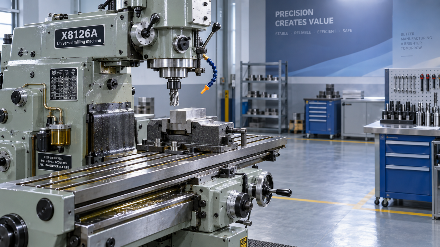
Verify lubrication, slides, and backlash before chasing accuracy
Machining accuracy begins with predictable movement. Before running the Universal milling machine X8126A, inspect the lubrication points and make sure the specified lubrication system has been operated according to the machine's normal procedure. Slideways should have an oil film, not dry streaks or excessive accumulated chips. Leadscrews, gears, and visible moving parts should not show unusual contamination or damage.
Run each relevant axis slowly by hand and feel for inconsistent resistance, sticking, or excessive free movement. Backlash is particularly important when positioning a feature from a dial or when approaching a coordinate after reversing direction. Operators should take up backlash consistently before setting a final position. Repeatedly reversing the handwheel to “find” the dimension can produce variable results, especially when the work involves close spacing, keyways, shoulders, or matched faces.
Gibs should be neither visibly loose nor over-tightened. A loose slide can contribute to chatter and dimensional variation under cutting load; an overly tight slide makes travel difficult and can accelerate wear. The correct adjustment is a controlled, smooth movement with no obvious looseness. If the table drops, shifts, or moves unexpectedly when locks are released, the setup should be stopped and the condition corrected.
Match the spindle, cutter, and speed to the actual operation
Check that the spindle taper, arbor, collet, drawbar, and cutter mounting surfaces are clean. Even a small chip or burr between a cutter holder and its seating surface can create runout. That runout may show up as an uneven finish, an oversize slot, or premature wear on one tooth of an end mill. Wipe the contact surfaces before assembly and make certain the tool is fully seated and tightened.
The cutter must suit the intended operation and material. Face mills, side-and-face cutters, slab mills, end mills, drills, and boring tools load the machine differently. A cutter selected only because it is available may still be unsuitable if its diameter, tooth count, overhang, or holding method cannot support the planned depth and width of cut.
Inspect cutting edges under good light. Replace or recondition tools with chipped edges, built-up material, obvious discoloration from overheating, or uneven wear. A blunt cutter often leads operators to increase feed pressure, which raises cutting force and can mask the real cause of poor finish.
- Confirm spindle rotation before bringing the cutter near the workpiece.
- Select a speed appropriate to cutter diameter, workpiece material, and cutter material.
- Set feed conservatively when using an unfamiliar setup, long tool extension, or interrupted cut.
- Use the correct arbor support or holder arrangement for the cutter type.
- Remove the spindle wrench and verify the drawbar or retention hardware is secure.
Speed selection deserves more than a quick glance at the gearbox or control setting. A large-diameter cutter at an excessive spindle speed can generate high peripheral speed and vibration even when feed appears modest. Conversely, operating too slowly can encourage rubbing rather than cutting, particularly with small tools. The target is stable chip formation, not simply the highest available removal rate.
Clamping must resist cutting force in every direction
Workholding is often the most consequential check because milling loads are intermittent and can pull, lift, or rotate a part. Confirm that the workpiece has clean contact surfaces and rests on proper parallels, supports, or locating faces. It should not sit on chips, damaged parallels, or uneven clamp points.
A vise is effective only when the part is supported and gripped in a way that resists the expected cutting direction. Long workpieces may need additional support. Thin parts can distort when over-clamped and spring back after machining, creating an apparent dimensional error that is actually a workholding problem. Irregular castings and fabricated parts may require dedicated clamps, step blocks, or a fixture rather than an improvised vise setup.
Check clamp bolt engagement, T-nut seating, and clearance between the cutter path and all clamp hardware. Keep clamps as low and as close to the work as the operation permits, while ensuring there is room for the cutter to exit. Before starting power feed, rotate the spindle by hand where safe to do so, or move the table through the planned path with the spindle stopped. This reveals many interference risks without sacrificing a tool or workpiece.
Test controls with the machine unloaded
Before cutting, verify the electrical supply condition, control functions, spindle start and stop response, feed engagement, axis direction, and emergency stop. Guards should be in place and adjusted so they reduce exposure to chips and rotating components without obstructing necessary visibility.
Pay special attention after a tooling change, maintenance activity, or shift handover. The previous operator may have left a feed direction, speed range, axis lock, or table orientation that does not suit the next task. A short unloaded run allows the operator to identify unusual noise from gears, bearings, or drive components before cutting load makes the symptom harder to interpret.
Coolant or cutting fluid arrangements should also be checked where used. Confirm that flow reaches the cutting zone without spraying electrical areas or creating a slip hazard. For operations performed dry, make sure chip evacuation remains adequate and that heat will not accumulate in a deep slot, pocket, or blind feature.
Use a first-pass check instead of trusting the setup
Even after a thorough inspection, the first cut should be treated as a verification cut. Start with a conservative approach, observe chip shape, listen for chatter, and watch whether the workpiece remains stable. Stop and investigate if the cutter begins rubbing, chips pack around the tool, the machine vibrates unusually, or the surface finish changes abruptly.
Measure the first critical feature before committing to a long batch or a finishing sequence. This is especially important after changing an arbor, collet, cutter, vise position, or table angle. It is faster to correct an offset or clamping issue after one trial pass than after every part has inherited the same error.
The same discipline applies when switching between machine types. A portable magnetic drill, for example, depends on clean ferrous contact and sufficient magnetic holding force before drilling begins. The Magnetic drill VD50EZ uses a 13,000 N magnetic base and is intended for core drilling up to 50 mm, but its pre-use concerns are different from those of a table-mounted milling operation. The comparison is useful because it reinforces a broader rule: the retention method must be assessed for the force and motion created by the process, rather than assumed from the tool’s appearance.
When to stop rather than proceed
An operator should not attempt to “work around” abnormal machine behavior by increasing clamp force, reducing feed to an impractical level, or making repeated adjustments during the cut. Stop the operation when there is unexplained vibration, a damaged tool holder, ineffective lubrication, unreliable controls, unusual spindle noise, loose workholding, or a collision risk that cannot be eliminated by planned travel.
For the Universal milling machine X8126A, the pre-operation routine is most effective when it follows the order of risk: secure the machine and workspace, confirm smooth and lubricated movement, install sound tooling, clamp the part for the expected cutting load, test controls, and validate the first cut. That sequence protects the operator while also protecting the dimensions and finish the job is expected to deliver.
