


How to check whether the X8126A table travel fits your fixture
Table travel is not the same as usable fixture capacity. A Universal milling machine X8126A can only support a fixture when the required cutter positions—not merely the fixture footprint—remain inside the machine’s X-, Y-, and Z-axis limits with safe clamping, spindle clearance, and access for every planned operation.
The decisive comparison is therefore between the machine’s working envelope and the fixture’s machining envelope. A fixture that physically fits on the table may still fail the evaluation if a tool cannot reach a feature near one edge, a vise jaw blocks the spindle, the column limits Y-axis approach, or the required Z height exceeds the spindle-to-table range.
Start with the actual X8126A configuration
“X8126A” should not be treated as a universal dimensional standard. Machine builders and export listings can differ in table size, available travels, spindle arrangements, accessory packages, and stated clearances. The evaluation should use the dimensional drawing and technical specification supplied for the exact machine configuration, including any vertical head, horizontal arbor support, rotary attachment, universal table, or raised subplate intended for use.
Record at least these machine values before reviewing the fixture:
- X-, Y-, and Z-axis travel;
- table length, width, T-slot layout, and permitted table load;
- spindle nose-to-table distance or vertical clearance range;
- spindle centerline-to-column distance, where applicable;
- clearance to guards, column, saddle, knee, and machine base;
- toolholder and cutter dimensions for the intended process.
Do not substitute table dimensions for travel dimensions. The table is the mounting surface; travel defines how far the workholding and workpiece can move relative to the cutter. In a universal milling machine, the usable envelope can also change materially when the table is swiveled or when the machining head is angled.
Define the fixture by its functional envelope
A fixture drawing should show more than its outside length and width. The relevant dimensions are the locations of all features that must be machined, inspected, or reached by a cutting tool. This includes datum surfaces, locator pins, clamps, side stops, hydraulic fittings, and any workpiece overhang beyond the baseplate.
For each required operation, establish the cutter center position relative to the fixture’s datum. Then identify the maximum and minimum X and Y coordinates that the machine must achieve. The resulting span is the minimum required planar travel. Add the distance needed to place the fixture datum at a practical clamping location on the table rather than assuming the datum can always sit exactly at the table center.
A useful planning expression is:
Required axis range = feature coordinate span + setup offset allowance + clearance allowance
The clearance allowance is not a generic fixed value. It depends on cutter diameter, toolholder profile, fixture walls, clamp geometry, and whether the operation is milling, drilling, boring, or side cutting. A large face mill may tolerate a different approach path from a long end mill; a boring head can introduce a much larger swept diameter than the nominal bore size suggests.
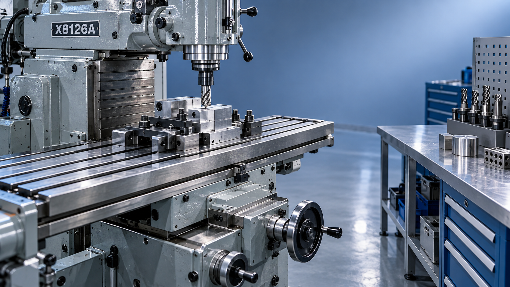
Check X-axis travel from tool access, not fixture length
Consider a fixture with an 800 mm baseplate and a workpiece feature close to each end. Even if the X8126A table is longer than 800 mm, the setup is unsuitable if the spindle cannot move far enough to machine both features after allowing for clamps and cutter overrun.
For end milling, the cutter normally needs to move beyond the finished edge to generate a clean surface. For slotting, approach and exit distances may be required. For drilling, the drill center must align with each hole position, but the fixture must also avoid obstructing chip evacuation or the toolholder body. The required X travel is therefore based on the farthest cutter-center positions, including the planned entry and exit movements.
Check whether the fixture is centered, offset, or intentionally positioned toward one side. An offset fixture can be valid when all machined features lie in one region, but it reduces reserve travel and can cause a collision with a table end, handwheel, guard, or support structure. If the process requires machining opposite faces after repositioning, evaluate each setup separately rather than averaging the envelope.
Y-axis clearance is often the hidden constraint
On compact universal mills, Y-axis capability is frequently limited by the relationship between the spindle, column, table, and the front edge of the fixture. A fixture may lie within nominal Y travel while the cutter cannot reach a rear feature because the workpiece, clamp, or toolholder approaches the column. Conversely, a front-side feature may require the table to move far enough forward that the fixture projects beyond a practical support position.
Measure from the spindle centerline to every critical fixture obstruction at the required tool position. Include the full body of the toolholder, not just the cutting diameter. This is particularly important with shell mills, angle heads, drill chucks, collet extensions, and horizontal arbors.
Where an X8126A is intended for both vertical and horizontal milling, conduct two separate checks. Horizontal milling introduces arbor length, support bracket position, cutter spacing, and potential interference with the fixture’s vertical elements. A fixture approved for a vertical end mill is not automatically suitable for a side-and-face cutter on an arbor.
Z-axis evaluation must include the complete stack-up
Z travel is commonly misjudged by comparing workpiece height with a published spindle-to-table distance. The machine must accommodate the entire vertical stack:
- table surface to fixture base;
- fixture base to workpiece datum;
- workpiece height and any clamp height above it;
- tool projection from the holder;
- required cutting depth, approach clearance, and safe retract distance.
The lowest spindle position must permit the tool to reach the deepest feature. The highest required position must allow tool change, part loading, probe use if applicable, and safe retraction without striking the fixture. A long tool can solve access around a clamp but may create a Z limitation, reduce rigidity, and increase deflection. It should not be treated as a simple clearance remedy.
On a knee-type or universal milling machine, distinguish between nominal vertical movement and the movement available in the chosen setup. Raising the workpiece with parallels, a subplate, or an angle plate consumes clearance. Tilting a universal table changes the effective height and shifts the workpiece laterally, so the X/Y evaluation must be repeated at the intended table angle.
Mounting feasibility is separate from motion feasibility
After confirming travel, verify that the fixture can be secured without compromising rigidity or access. Its mounting-hole pattern must align with the X8126A table’s T-slots, or an engineered adapter plate must be used. Check stud diameter, T-nut engagement, slot spacing, and whether the fixture blocks access to tightening points.
Fixture mass and its center of gravity also matter. A setup within the rated table load can still be problematic if the mass is heavily cantilevered, especially during table movement or when machining at the travel limits. The concern is not only static capacity but also bending load on the table, saddle, and clamping arrangement. A large fixture may require additional support, a smaller workholding assembly, or a different machine architecture.
Use a coordinate-based interference review
The most reliable approval method is to model the machine, fixture, workpiece, clamps, and representative tools in CAD. If a full machine model is unavailable, create a simplified envelope model using manufacturer drawings. Simulate axis-limit positions and the actual tool paths for every operation, including retracts and tool changes.
Pay particular attention to conditions that are easily omitted from a static model:
- clamp handles or hydraulic lines extending into the cutter path;
- tool-change clearance for the longest tool;
- spindle-head or quill movement near tall fixtures;
- swiveled-table positions and their shifted workpiece envelope;
- operator loading clearance and access to fixture fasteners;
- chip accumulation areas that may obstruct seating or motion.
A physical dry run remains valuable before production release. Use the real holder and a representative tool length, move at reduced speed, and verify limit margin at the most demanding positions. This does not replace drawing-based validation; it confirms that omitted hardware details and actual setup conditions have not changed the result.
Keep a reserve margin rather than designing to nominal limits
Using 100% of a published axis travel is rarely a robust production decision. Fixture alignment variation, tool-length changes, replacement clamps, and datum adjustments consume margin. A setup that only works when the fixture is positioned to within a few millimeters can become non-repeatable after routine maintenance or changeover.
The required reserve depends on process sensitivity and setup repeatability, but it should be explicitly recorded in the approval sheet. The same applies to Z clearance: a theoretically valid tool path may be operationally poor if there is insufficient room for safe loading, measurement, or chip removal.
Where the fixture envelope is consistently close to the limits of an X8126A, a machining center with a documented three-axis envelope can offer a clearer basis for comparison. For example, the Vertical Machining Center VMC855 lists 800 mm X travel, 550 mm Y travel, 550 mm Z travel, a 1000 × 550 mm table, and a spindle-nose-to-table range of 120–670 mm. Those values do not establish suitability by themselves, but they illustrate the dimensional data needed to evaluate a fixture systematically.
Approval should be based on a signed setup envelope: exact machine configuration, fixture revision, workpiece maximum condition, clamp arrangement, tool list, axis ranges, vertical stack-up, load, and identified interference points. Once these items are documented, the question changes from “Does the fixture fit the table?” to the more useful one: “Can every required operation be performed safely, repeatably, and with adequate process margin?”
