


Milling Machine Accuracy Standards Worth Checking Before Acceptance
Start with the acceptance standard, not the sales brochure
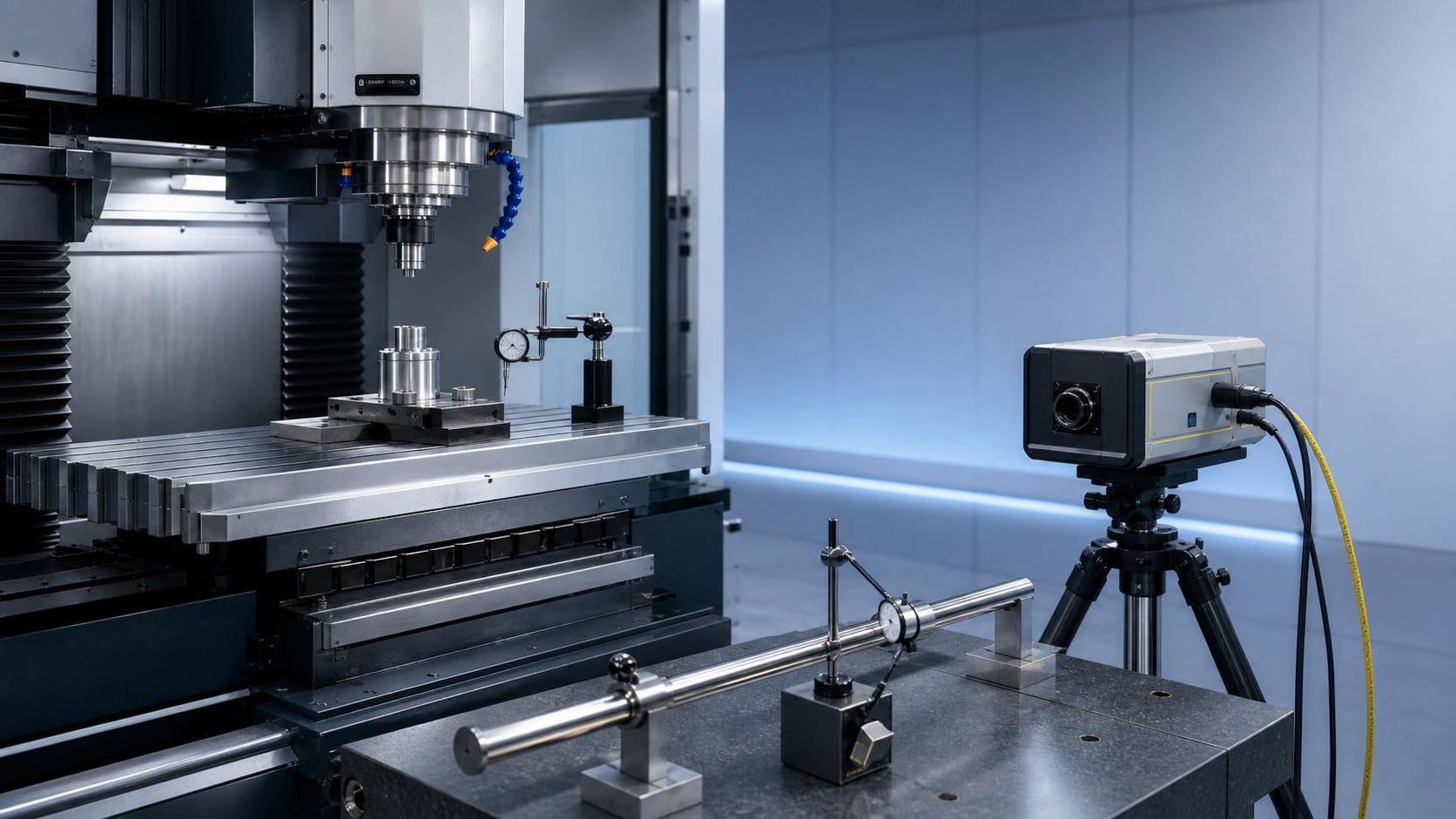
When a milling machine arrives on site, the real question is simple: can it hold the accuracy your process needs once it is installed, warmed up, and cutting under load? That matters more than a polished test sheet. For technical evaluators, acceptance should focus on measurable machine behavior: positioning accuracy, repeatability, spindle condition, axis geometry, table movement, and the machine’s stability during practical tests. If any one of those is weak, part quality usually drifts long before operators can explain why.
A good milling machine inspection is not about creating more paperwork. It is about finding the gap between nominal specs and usable production accuracy before the machine enters the line. That is where most downstream trouble starts: taper wear showing up as chatter, axis backlash hiding inside contour errors, or a table that looks fine in a static check but loses alignment across travel.
Check the reference documents before touching the machine
Before any indicator comes out, compare three things: the contract spec, the maker’s accuracy inspection record, and the acceptance method you plan to use on site. This sounds basic, but many acceptance disputes begin here. One document may state positioning accuracy at full travel, another may report only repeatability, and a third may be based on no-load conditions. Those are not interchangeable.
For a milling machine, make sure the evaluation method defines the travel length tested, the measuring instrument used, thermal condition, and whether compensation values were active in the control. A compensated machine can look excellent on paper and still behave poorly after maintenance or parameter loss. If compensation is enabled, record that fact as part of acceptance, not as a footnote.
Positioning accuracy and repeatability are not the same problem
Evaluators often focus on the positioning number because it is easier to quote. In practice, repeatability is what exposes whether the machine will behave consistently in production. A machine can be corrected for absolute position; it is much harder to work around unstable return behavior.
- Test each axis near both ends of travel and around the area where most parts will actually be machined.
- Approach the same point from both directions. Direction-change error often reveals backlash, servo lag, or ballscrew condition.
- Run multiple cycles, not one. A single good result can hide instability.
If repeatability changes noticeably after warm-up, note it. Thermal growth is normal; unstable thermal behavior is not. What you want is predictable drift that can be managed, not random scatter across the shift.
Look closely at spindle runout, taper condition, and real cutting stability
Spindle accuracy is where acceptance moves from numbers to consequences. Excessive runout affects hole location, surface finish, tool life, and size control. Check runout at the spindle taper and, if appropriate for the machine type, at a test mandrel or toolholder extension. A clean taper matters here. Dirt, minor damage, or poor contact can distort the reading enough to send the team in the wrong direction.
Do not stop at idle measurement. Run the spindle through low, medium, and higher speed ranges and listen for bearing noise, heat rise, and vibration. A machine may pass a static runout check yet still cut badly once speed increases. If your parts depend on fine finishing or tight bores, this step deserves more time than the general geometry check.
Table geometry tells you whether the machine can hold alignment across the work zone
Flatness, straightness, squareness, and parallelism are not abstract inspection items. They decide whether a part can be machined consistently from one corner of the table to the other. On a milling machine, errors here show up as tapered surfaces, inconsistent slot depth, or features that go out of relation as the setup moves.
Pay attention to geometry over usable travel, not only at the center. Many machines spend their lives cutting in a limited area, and wear concentrates there. If the machine will process larger plates or fixtures, extend the check far enough to cover that footprint. Acceptance done only near home position is usually too optimistic.
Backlash, lost motion, and servo response deserve their own check
Backlash is easy to underestimate because some controls mask it reasonably well in simple moves. It becomes harder to ignore when circular interpolation, pocket corners, or reversing cuts are involved. During acceptance, command short reversals and compare actual response. If the machine hesitates, overshoots, or settles differently each time, do not file that under “operator tuning.” It usually points to a mechanical or servo issue that will matter later.
This is also where application matters. A general-purpose shop may tolerate more lost motion than a line cutting mold components or precision fixtures. The acceptance standard has to match the parts the machine is expected to produce.
Run a practical machining test that matches production reality
A witness cut is worth more than a stack of isolated readings, provided the test is chosen well. Use material, tooling, and cutting conditions close to actual use. Then inspect the result for size stability, surface finish, hole position, perpendicularity, and repeatability over repeated runs. If the acceptance sample is too easy, the machine tells you very little.
This principle also helps when reviewing machines adjacent to the milling process. For example, if your line includes drilling and secondary operations, the travel envelope and spindle range of Radial Drilling Machine Z3050 can be reviewed in the same practical way: compare its 50 mm maximum drilling diameter, MT5 spindle taper, 32-2500 rpm speed range, and 315 mm spindle travel against the actual hole sizes, reach, and setup constraints in your shop. The method is the same even when the machine type changes: judge capability against work, not catalog language.
Do not ignore installation and environmental conditions
Some acceptance failures are not machine build issues at all. Leveling, foundation stiffness, coolant splash into measuring areas, unstable shop temperature, and poor power quality can all distort the result. That does not mean they should be ignored. It means the acceptance record should clearly separate machine condition from site condition. If the floor settles or the machine is tested before it reaches thermal stability, repeating measurements later is not optional.
One common mistake is signing off after geometric checks but before the machine runs long enough to reveal heat-related drift. Another is accepting a good empty-table result without checking accuracy under fixture load. Both create trouble that shows up only after handover.
Record what was measured, how it was measured, and under which condition
A useful acceptance report is detailed enough that another evaluator could repeat it and understand the outcome. Include machine status, warm-up condition, active compensation, measuring equipment, test positions, and whether the result came from no-load checks or cutting tests. Without that, the numbers lose value fast.
If you need a practical order, use this one: verify documents, stabilize the machine, inspect spindle condition, check axis positioning and repeatability, measure geometry across the actual work zone, then run a cutting test representative of production. That sequence tends to expose the expensive problems early, while there is still time to correct them before final acceptance.
