


How thin steel affects magnetic holding force on the Magnetic drill VD50
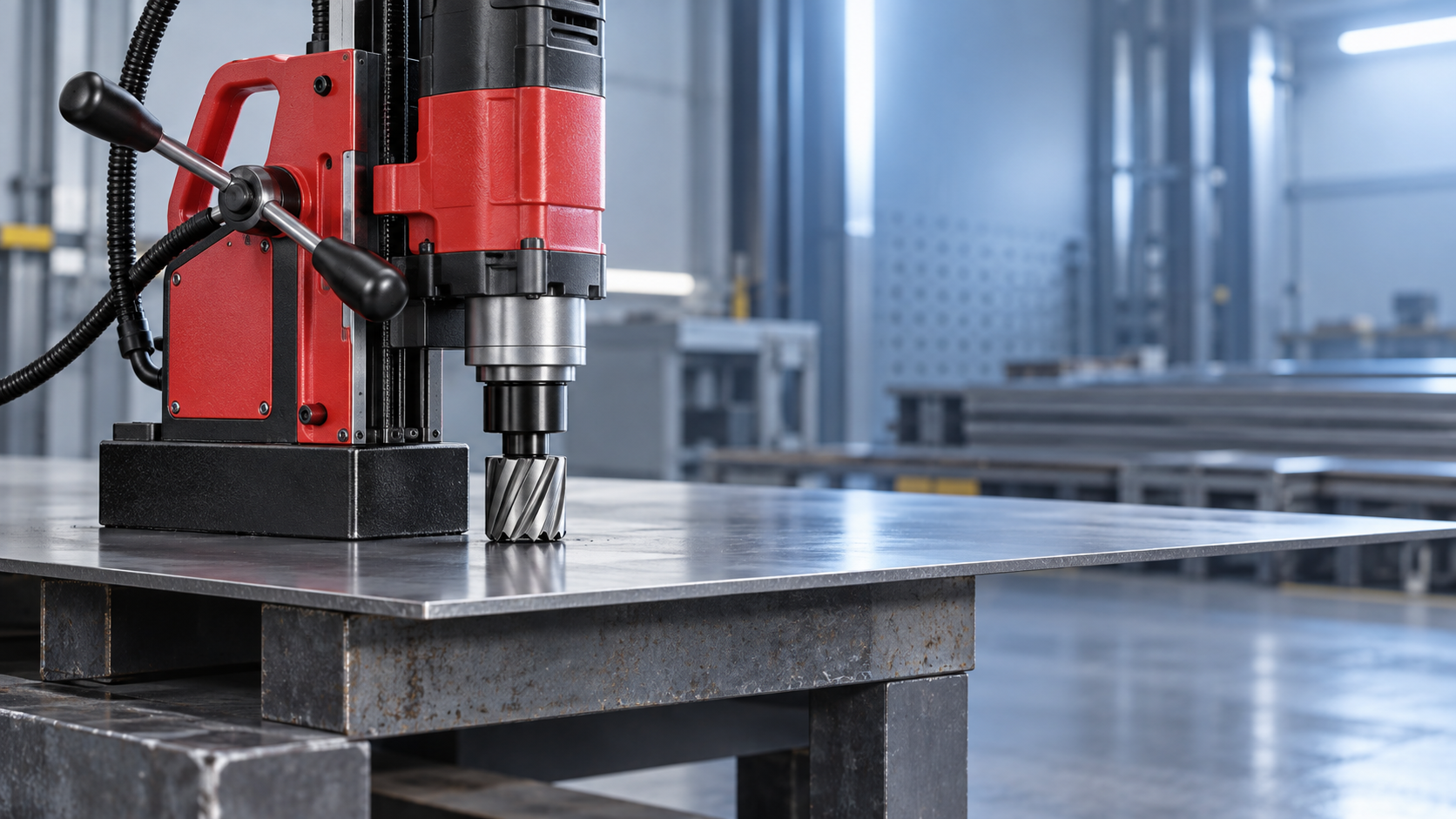
Thin steel is not simply a weaker version of thick steel for a magnetic drill. It changes the magnetic circuit beneath the base, reducing the amount of flux the workpiece can carry and increasing sensitivity to surface condition, vibration, and drilling torque. For the Magnetic drill VD50, this means that a base that appears firmly attached during a static check may provide an inadequate safety margin once the cutter enters the material.
The critical point is that magnetic holding force is a system value, not a fixed number produced by the magnet alone. Magnet design, steel thickness, steel grade, contact area, paint or scale, workpiece geometry, and the direction of applied drilling loads all determine whether the drill remains stable.
Why steel thickness changes the magnetic circuit
A magnetic drill base creates a closed magnetic path: flux leaves one pole of the magnet, travels through the steel workpiece, and returns through the opposite pole. A thick, low-carbon ferromagnetic plate generally provides a low-reluctance path for that flux. The magnetic circuit is efficiently completed, allowing the base to develop close to its intended holding performance.
When the steel is thin, the plate can become the limiting part of that circuit. It has less cross-sectional area to carry magnetic flux and may approach magnetic saturation. Once the material is saturated, adding magnetic excitation does not produce a proportional increase in useful holding force. Some flux leaks through air around the workpiece rather than passing through the steel between the poles. The result is lower normal clamping force at the drill base.
This effect is especially important because manufacturer-rated magnetic force is commonly established under controlled conditions: clean, flat, sufficiently thick, mild-steel test material with full base contact and a load applied perpendicular to the surface. Field drilling rarely reproduces those conditions. A thin painted panel, a corroded structural member, or a plate close to an edge can provide materially less retention than a nominal rating might suggest.
Holding force is not the same as resistance to drilling movement
Even where the VD50 base develops enough downward attraction to remain attached, drilling generates forces that do not act only normal to the surface. Annular cutters and twist drills create torque around the spindle axis. Feed pressure, cutter snagging, breakthrough, and chip packing can introduce lateral or rotational loads. Those loads try to make the machine slide or pivot rather than pull directly away from the steel.
The practical resistance to sliding depends partly on friction:
Sliding resistance ≈ magnetic normal force × coefficient of friction
That relationship explains why thin material is a compounded risk. Reduced steel thickness lowers magnetic normal force; oil, coolant, mill scale, paint, or surface oxidation can then further reduce friction. A base may not detach vertically, yet still rotate slightly under torque. Even minor movement can damage an annular cutter, enlarge the hole, break a pilot pin, or place the operator in the line of an unstable machine.
Rotational instability is often more relevant than a simple pull-off concern. A magnetic base has a finite footprint. If the resultant drilling load acts near an edge of that footprint, the drill can begin to pivot. Thin stock makes this more likely because the available magnetic force is already reduced and because lightweight sheet or plate can flex under load.
Thickness is only one variable in “steel”
Technical evaluations should avoid treating all steel of the same gauge as magnetically equivalent. Carbon steels used for fabricated structural work are generally suitable magnetic substrates, but their magnetic properties can vary with composition, heat treatment, residual stress, and forming history. Austenitic stainless steels, aluminium, copper, and many non-ferrous alloys cannot provide a conventional magnetic-drill holding path at all. Some stainless grades are partially magnetic, but their behavior should not be assumed from appearance or grade family alone.
Work-hardened, highly formed, or thin sheet can also behave differently from a flat mild-steel coupon. A steel component may be magnetic enough for a hand-held magnet to adhere while still being unsuitable for a magnetic drilling operation. Hand adhesion is not a meaningful validation of resistance to drilling torque, feed force, and vibration.
Geometry can reduce performance as much as thickness. Narrow strips, members with nearby openings, flanges, curved surfaces, and locations close to an edge restrict the effective magnetic return path. A base spanning a slot or positioned partly over a void does not have full support, even if the nominal material thickness elsewhere on the component is adequate. Weld seams, uneven galvanizing, and local distortion can also create air gaps between the magnet and steel. Air gaps are highly detrimental because air has far higher magnetic reluctance than ferromagnetic steel.
Why surface preparation matters more on thin steel
On thick, clean plate, a small layer of coating may reduce holding force without immediately causing instability. On thin steel, the system has less reserve. Paint, galvanizing irregularities, burrs, weld spatter, swarf, and trapped coolant can therefore become decisive.
The base contact surface should be clean, dry enough to maintain friction, and flat against the workpiece. Removing loose scale and heavy coating at the base location is not a cosmetic step; it reduces the effective air gap. The underside of the magnetic base also needs inspection. Metal chips caught under the poles can prevent full contact and create a tilt condition that is difficult to detect before drilling begins.
Surface cleaning must not be confused with permission to drill on unsupported thin stock. A clean interface improves the available magnetic circuit but cannot compensate for a plate that is below the drill manufacturer’s stated minimum thickness or a workpiece that lacks stiffness.
How to evaluate VD50 suitability without relying on a nominal force figure
The first reference should be the VD50 operating documentation. Its specified minimum workpiece thickness, acceptable material condition, permitted orientations, safety-chain requirements, cutter diameter limits, and feed instructions take precedence over general rules of thumb. If a minimum thickness is not clearly stated, it should be obtained from the manufacturer rather than inferred from magnet dimensions or a quoted holding-force value.
A useful assessment separates the application into the following questions:
- Is the workpiece ferromagnetic and sufficiently thick across the full magnetic-base footprint?
- Is the base fully supported by solid, flat material, rather than bridging an edge, opening, narrow flange, or curved section?
- What drilling torque and feed force will the selected cutter, diameter, and material generate?
- Will the operation be horizontal, vertical, or overhead, and does that orientation introduce gravity-driven slip or falling-tool hazards?
- Can the workpiece itself flex, vibrate, or move during breakthrough?
- Is an independent retention method required by the equipment instructions or site safety procedure?
Static attachment should be checked before starting, but it is not a substitute for this assessment. A controlled pull test can reveal grossly inadequate adhesion, yet it does not fully simulate torsional loading or a cutter catching in the hole. The relevant engineering question is whether the complete setup has adequate margin under the highest credible operational load, not whether the magnet can hold the machine’s dead weight.
Operational controls for thin material
Where drilling on relatively thin but permitted steel cannot be avoided, the process should be made less demanding. Use a sharp cutter, appropriate cutting fluid, controlled feed, and a speed suited to cutter diameter and material. Excessive feed increases torque and can cause the cutter to grab; insufficient feed can rub and generate heat, which accelerates cutter wear and raises the chance of erratic loading.
Backing the workpiece with a thicker ferromagnetic plate can improve the magnetic return path, provided the backing is flat, secure, and supports the entire base area. It must not introduce a gap, create a separate loose component, or obstruct the drilling path. In some fabrication conditions, a clamped drilling fixture, a purpose-designed support plate, or machining before assembly is safer than relying on a magnetic base on thin stock.
For repeated holes in parts that are too thin for reliable magnetic drilling, the manufacturing route should be reconsidered rather than forcing the application. Components that require turning operations alongside controlled secondary features may be better handled in a rigid machine-tool setup; for example, the Slant Bed CNC Lathe TCK52 represents a different class of fixtured machining equipment, not a substitute for a magnetic drill on structural work.
The safety margin must account for real drilling conditions
Thin steel does not automatically prohibit use of the Magnetic drill VD50, but it removes margin from the most important safety function of the tool: stable magnetic retention. The correct threshold is therefore not a visual judgement that the base “seems strong.” It is the documented minimum thickness and application envelope specified for the machine, verified against material type, contact condition, geometry, orientation, cutter load, and independent restraint requirements.
Where any of those conditions depart from the documented basis for magnetic holding force, the safe assumption is that the available retention is lower than the headline figure. In magnetic drilling, that conservative judgement protects hole quality, tooling, the workpiece, and—most importantly—the operator.
