


Common Thermal Drift Issues in CNC Machine Tools and Remedies
Where Thermal Drift Shows Up First
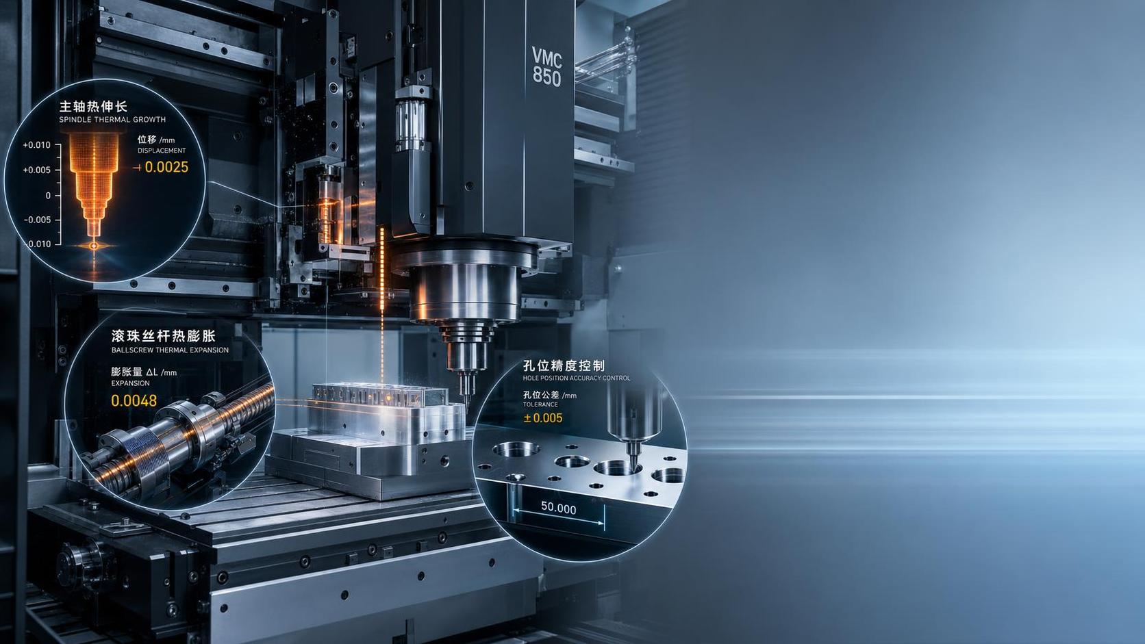
Thermal drift rarely announces itself as a dramatic machine fault. More often, it appears as a quiet change in size after the machine has been running for an hour, a bore that moves out of tolerance during a long cycle, or a part that measures differently in the morning than it does after lunch. In CNC machine tools, the heat source is usually not a mystery. The spindle generates heat at speed, feed drives warm up under repeated acceleration, ball screws expand as they cycle, and even the shop environment can shift the machine structure enough to affect precision.
This matters most where dimensional consistency is judged across batches rather than on a single first-off part. A machine may pass an initial trial cut, yet still create problems in continuous production if its thermal behavior is unstable. That is why technical evaluators do not look only at static accuracy figures. They also ask how the machine behaves after warm-up, under higher spindle load, and through different ambient conditions.
For shops machining aluminum housings, valve blocks, mold plates, or medium-tolerance steel components, thermal drift tends to show up in three places first: spindle growth affecting Z-axis results, axis expansion changing hole position, and changing geometry between roughing and finishing cycles. Those patterns are common across many CNC machine tools, but the severity depends heavily on duty cycle and installation conditions.
Not Every Shop Sees the Same Problem
A machine in a climate-controlled toolroom behaves very differently from one on a production floor near loading doors, coolant mist, and forklifts. That distinction gets overlooked. Buyers sometimes focus on spindle speed or travel range and assume thermal stability will take care of itself. It does not.
In a small-batch precision environment, the main concern is often repeatability after setup changes. Operators may run short programs, stop frequently for inspection, then restart. The machine never reaches a fully stable heat state, so dimensional variation can come from repeated warm-up cycles. In contrast, high-utilization production lines usually have the opposite problem: once the spindle, motors, and screws are fully loaded for hours, the structure settles into a hotter condition and compensated values can drift away from the cold-start reference.
Long Z-axis moves and sustained spindle use deserve extra attention. On vertical machining centers, spindle nose growth can directly affect pocket depth, surface finish consistency, and step height control. That is one reason machine construction matters. A rigid platform with a one-piece cast bed, stable guideway layout, and properly matched drive system generally offers a better foundation for managing thermal movement than a lighter structure that changes shape more easily under load.
What Usually Causes the Drift
The spindle is the most discussed heat source, and for good reason. At higher speeds, bearing heat and motor heat can shift the spindle centerline or produce axial growth. On jobs requiring tight depth control, that change may be more important than raw spindle power. A belt-driven spindle running at 10000 rpm, for example, can be entirely suitable for general precision work, but its thermal behavior still depends on bearing preload, lubrication, housing design, and how long the machine stays under load.
Ball screws are another frequent contributor. Repeated rapid traverse and feed reversals warm the screw and nut assembly, especially on machines running dense toolpaths or frequent positioning moves. As the screw expands, axis position shifts. Machines with larger screw diameters, appropriate servo tuning, and stable support structures usually manage this better, but the application still matters. A contour-heavy program with thousands of short moves creates a different thermal pattern than face milling large flat surfaces.
Then there is the environment. Direct sunlight on one machine column, poor coolant temperature control, and a five- to eight-degree swing between day and night can all disturb what appears to be a healthy machine. These are not exotic failure modes. They are routine site conditions in many general mechanical equipment workshops.
Remedies That Actually Help on the Floor
The most effective remedy is not always an advanced compensation package. Sometimes it is process discipline. Warm-up routines remain useful because they bring spindle and axes into a predictable thermal state before critical finishing begins. Shops that skip this step often end up chasing offsets through the shift.
Machine selection also has a direct role. When thermal stability matters, evaluators should look beyond brochure claims and compare structure, drive configuration, and achievable accuracy under realistic load. A vertical machining platform such as Vertical Machining Center VMC1580 becomes relevant in this discussion not because of branding, but because the underlying design choices affect heat behavior. Across its VMC650, VMC855, VMC1160, VMC1270, and VMC1370 variants, the platform uses a one-piece cast bed, high-precision ball screw, and servo drive system, with published positioning accuracy down to ±0.003mm and repeatability of ±0.004mm in the provided specification set. Those figures do not eliminate thermal drift by themselves, but they indicate the machine is built for controlled motion rather than rough positioning only.
A few practical measures usually give the best return:
- Run a consistent warm-up cycle before finishing critical features.
- Keep coolant temperature reasonably stable, especially on long production runs.
- Separate roughing and finishing when heavy stock removal is driving spindle and axis heat.
- Inspect part trends over time, not just individual dimensions.
- Install the machine away from direct drafts, doors, and uneven radiant heat.
How to Judge Risk Before It Becomes Scrap
One common mistake is to treat thermal drift as a machine-only issue. In reality, it is a system issue involving the machine, tooling, cycle design, inspection timing, and workshop conditions. A machine may hold tolerance well on medium-duty prismatic parts yet struggle on long unattended cycles with aggressive spindle utilization. That does not mean the machine is inadequate; it means the application envelope has changed.
This is where specification reading should become practical. Travel size, screw diameter, guideway width, spindle torque, table load, and feed system capacity all influence how a machine behaves thermally during real cutting. If a shop regularly runs heavy fixtures or large plates, a model with stronger structural support and higher load capacity usually gives more stable results over time than a smaller frame pushed to its limit. In that sense, the right CNC machine tools are chosen not by maximum speed alone, but by how calmly they hold geometry when the workday is no longer ideal.
For evaluators comparing machines, the useful question is simple: what happens after two hours of real production, not ten minutes of demonstration cutting? That is usually where thermal drift stops being a theory and starts becoming either a manageable variable or an expensive habit.
